You'll need the following measurements for the form that you will be filling out.
We've included a printable (PDF) worksheet for your convenience.
We've included a printable (PDF) worksheet for your convenience.
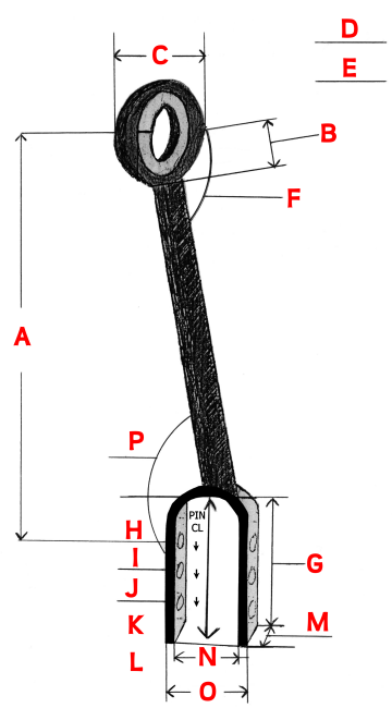
A: Center line length from top pin at ball socket to top pin hole of bottom clevis. Measure your stationary side link, usually
on the left side of the tractor
or
A1: If both of your side links are adjustable, the collapsed length and the maximum extended working length (two measurements needed)
B: Center line length from top pin at ball socket to top of side link shaft
C: Outside diameter of ball socket housing
D: Ball socket pin diameter
E: Ball socket width
F: Amount of degrees of the top ball socket from the side link shaft; is the pin 90° to the side link shaft or something else?
G: Inside total depth of bottom clevis
H: Center line distance of top clevis pin hole of bottom clevis to inside top of bottom clevis
I: Center line distance of second bottom clevis hole from top hole of bottom clevis
J: Center line distance of third bottom clevis hole from second hole (should be same as I)
K: Slot for floating link clevis, contact us if your side link has this
L: Pin diameter size for lower clevis
M: Clevis width
N: Clevis width inside
O: Clevis width outside
P: Degrees of bottom clevis to the side link shaft. A straight clevis would have the clevis pin 90° to the side link shaft. How many degrees is your clevis pin to the side link shaft?
Tractor make
Tractor model
Tractor model
| Worksheet | Submission Form |
Fit Rite Hydraulics